Modern induction heating industry needs high-power, high power density, continuous large batch and environmentally clean induction heating equipment, which poses new challenges to the manufacturers of induction equipment. The manufacturers of induction heating equipment have done a lot of research and practice in this field. From the connection mode of coils and capacitors, there are two kinds of circuits with series inverter and parallel inverter. From the analysis of two kinds of inverter circuits, users can correctly select medium frequency induction power supply.
Analysis of the principle of two inverters
One, series inverter circuit
1、Schematic diagram of a series inverter circuit
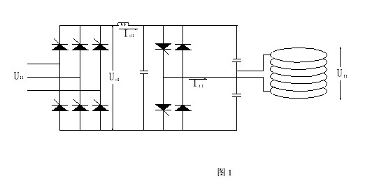
2、Main parameters of a series inverter circuit
⑴The effective value U of the medium frequency voltage base wave component of the inverter outputal
⑵The effective value I of the output current of the inverteril
η:Efficiency of inverter circuit
⑶output power P

⑷Maximum voltage for inverter thyristor UDRM

⑸Forward average current flowing through the invert thyristor Ivk

⑹The current flowing through the coil is equal to the intermediate frequency output current flowing through the inverter thyristor.

⑺The coil voltage is equal to Q times of the thyristor output intermediate frequency voltage.

Two, schematic diagram of parallel inverter circuit
1、Schematic diagram of parallel inverter circuit

2、Main parameters of parallel inverter circuit
⑴The effective value of the medium frequency voltage base wave component in the output of the inverter Ua2

⑵Output current value of inverter Ii2

⑶Output power P

⑷Maximum voltage for inverter thyristor UDRM
⑸Forward average current flowing through the invert thyristor Ivk

⑹The current flowing through the coil is equal to Q times the output current of the thyristor flowing through the thyristor.

⑺The coil voltage is equal to the output thyristor output intermediate frequency voltage.

Comparison of two inverters
First, inverter voltage
From the formula (1-1) (2-1), we can see that under the same power and the same input voltage, the output intermediate frequency voltage of the parallel inverter circuit is higher than that of the series inverter circuit.From the formula (1-4) (2-4), it is seen that the voltage of the thyristor is higher than that of the series inverter circuit.However, from (1-7) (2-7), it is seen that the voltage of the series inverter coil is higher than that of the parallel inverter.
Second, inverter current
From the formula (1-2) (2-2), we can see that under the same power and the same input voltage, the output intermediate frequency current of the series inverter circuit is higher than that of the parallel inverter circuit. From the formula (1-5) (2-5), it is seen that the thyristor flow in series inverter is higher than that in the parallel inverter circuit.If the thyristors connected in series choose parallel, the current flowing through each thyristor can also be designed same to parallel thyristor. However, from (1-6) (2-6), it is seen that the current of the inverter coil is higher than that of the series inverter current, resulting in the copper loss of the parallel inverter coil is larger than that of the series inverter.
From the formula (1-3) (2-3), we can see that both the parallel inverter circuit and the series inverter circuit through the inverter thyristor output AC current Iiand voltage Uato the copper coil,because the inverter output current and voltage are not the same phase,there is a phase angleΦ,According to the difference between the output power and the state of the electric furnace,the phase angle changed,and the power input to the coil of the electric furnace,in addition to the product of current and voltage, it is also multiplied by an inverter power factor COSΦ。
The thyristor can only flow through the forward current. When the thyristor is selected for the inverter design, the main consideration is the node temperature of the internal PN junction when the thyristor flows through a certain current. Considering the minimum conduction angle, the node temperature of the internal PN junction is still not more than the safety temperature when the thyristor flows through the maximum current. Both the parallel inverter circuit and the series inverter circuit must abide by this principle.
There is a point of view,the output current of the series inverter circuit with the same power is larger than that of the parallel inverter circuit, so the thyristor of the series inverter circuit is easy to damage and the service life is short.
Because the output current of inverter circuit is different, the same size thyristor can not be used. When the invert thyristor is used in parallel, as long as the minimum conduction angle is at the minimum pass angle, when the thyristor flows through the maximum current, the temperature of the node in the inner PN junction is the same, not exceeding the safety temperature. It is the same for the load of each thyristor. There is no problem that the thyristor is easily damaged and the service life is short. If the junction temperature of thyristor of series inverter circuit is designed, it will shorten the service life.
With the continuous development of high-power thyristor (SCR) manufacturing technology, thyristors with diameter of 100mm have been used in medium frequency induction power supply. However, the current and voltage of a single thyristor are limited. A large power supply, the maximum output to the coil is more than ten thousand amperes. That is, the parallel inverter circuit also needs the parallel use of the invert thyristor. The success or failure of the thyristor's parallel use is mainly based on the trigger and current balancing measures of the thyristor. Design. The high-power thyristor triggered signal is isolated from the power supply, without the direct drive design of the pulse transformer output isolation. The modern electronic controller component field effect tube (MOSFET) has a very fast response time, acts as the last output driver, and causes the trigger signal of the thyristor
with enough trigger current and fast rising speed, the parallel thyristor can be opened at the same time, thus ensuring the reliable operation of the parallel thyristor.
Some series inverter circuit manufacturers have output copper short circuit test before each equipment is out. When the equipment is running, the copper row is suddenly short circuited and the equipment can automatically protect the shutdown. No parts are damaged. After the reset, the equipment can be reinvested in normal use. Only through this test, the equipment can be out of the factory. This is the performance of the manufacturer's full confidence in the parallel thyristor technology in the series inverter circuit, and the best refutation of the argument that the thyristor is easily damaged and the service life is short in the series inverter circuit.
Three, rectifying link processing
The intermediate frequency induction power rectifier usually uses three phase bridge, six phase bridge or twelve phase bridge thyristor rectifier. Three phase bridge rectifier has six thyristors, each thyristor needs a trigger pulse, which requires six trigger pulses, so it is also called 6 pulse rectification. The six phase bridge rectifier is also called the 12 pulse rectifier. The twelve phase bridge rectifier is also called the 24 pulse rectifier.
1、串联逆变电路
串联逆变电路只需要一个固定输出电压、可变输出电流的直流源,不需要改变直流电压来调整逆变输出功率,只是在运行时,直流电流输出不同。所以桥式整流器直流输出电压始终是最高电压;不需要改变整流器晶闸管的触发导通角;控制起来也简单可靠。但是不意味着不监视整流器工作状况,由于仍然采用晶闸管桥式整流器,因此在有故障情况下,可以通过撤销整流器晶闸管的触发脉冲,只要 50 赫兹中的一个周期 20
毫秒时间迅速彻底隔离外部输入与逆变器的联系。
2、并联逆变电路
并联逆变电路需要一个可变输出电压、可变输出电流的直流源,需要改变直流电压来调整逆变输出功率,桥式整流器直流输出不同的直流电压是通过改变晶闸管的触发导通角来完成的。桥式整流器的控制是并联逆变电路的重要部分,必须精确控制整流晶闸管的触发导通角,许多参数最大值的限制都是通过改变触发导通角来完成的。在有故障情况下,也是可以通过撤销整流器晶闸管的触发脉冲,隔离外部输入与逆变器的联系。
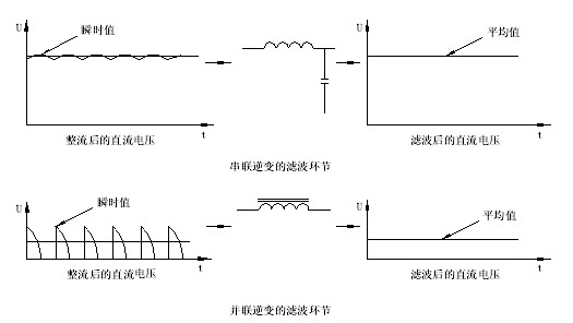
四、直流滤波环节
1、串联逆变电路
在桥式整流器直流输出端串联电抗器加并联电容器的组合滤波,输出直流电压和电流平稳;一般电抗器采用无铁芯的电抗器,有效降低电抗器发出的噪音。同时由于电容滤波的作用,也充分抑制逆变中频的谐波分量反馈到外部电网。
2、并联逆变电路
只在桥式整流器直流输出端串联电抗器,通常为了在低直流电压输出时,也能保持直流电流的连续,必须设计足够大的电感量,需要带铁芯的电抗器。电抗器发出噪音也相应大一些。
五、谐波分量的分析
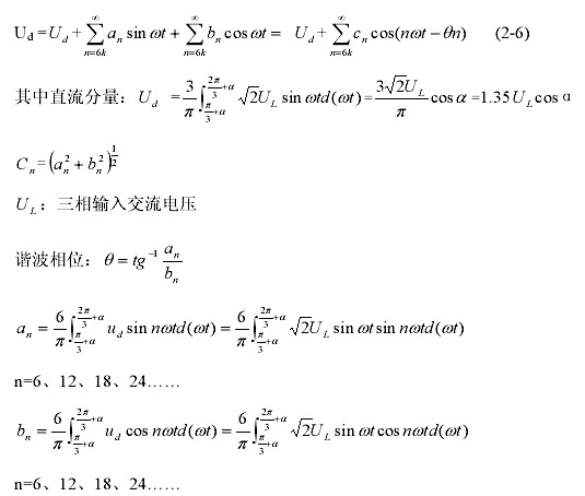
整流输出的脉动直流电压都是周期性的非正弦函效的直流分量加上各次正弦函数。负载上的电压可以对应各次谐波电压,产生各次谐波电流,负载上的电流合成。
以三相桥式全控整流电路为例,直流电流连续时,何值,负载直流电压的傅氏级数表达式为:
根据上述关系,我们可以计算出以n为参变量,各次谐波幅值的标么值 对应整流器晶闸管的延迟触发角α的关系曲线,见图5。

可以看出,采用当α=0°时,谐波幅值最小;当α=90°时,谐波幅值最大;谐波幅值随整流器晶闸管的延迟触发角α的增大而增大。
1、串联逆变电路的整流器晶闸管的延迟触发角α始终为0,所以各次谐波幅值都是最小的值。
2、并联逆变电路的整流器晶闸管的延迟触发角α是变化的,如果α=30°时,各次谐波幅值大约就是α=0°时的两倍;α角度变大时,各次谐波幅值就成倍地变大。
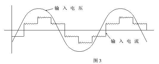
由于晶闸管是一个非线性的电气元器件,所以由晶闸管组成的中频感应电源对于外部输入电源是一个非线性的负载。也就是在一个周期性的正弦电压输入时,它的阻抗是变化的,电流不是正弦波形,见图3。在电流突变时在正弦电压波形上有短时尖峰。
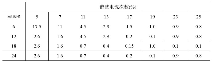
对于外部三相输入电流,是一个方形台阶波形,可以用傅氏级数的形式分解成等效的(50Hz或 60Hz)基波分量加上各基波奇数倍次的正弦函数分量。但是考虑到晶闸管的换流、三相电压微小的不平衡等因数,IEEE综合理论计算和实际测量值,给出了不同整流配置情况下各次谐波电流幅值和基波电流幅值之间的数量关系。
为了使得大功率中频感应电源产生的谐波对公共电网的影响符合设备使用地供电局的要求,我们必须在选购设备时,考虑到以下因素来减少谐波的产生量。
1、全波整流,不调整直流输出电压。在不增加设备制造费用的情况下,任何时候轻易得到最高的功率因数和最小的谐波发生量。
2、针对低次谐波电流超标,可以适当增加整流脉冲数量。如果某台6脉冲整流的中频电源产生的5、7次谐波电流超标,可以采用 12脉冲整流,这样就可以大大减小5、7次谐波电流值。在某些超大功率中频电源,可以采用 24脉冲整流,可以大大减小5、7、11、13次谐波电流值。
六、低功率运行时的功率因数
三相整流器的功率因数可以用  表示,忽略整流器晶闸管的换流角的话,用
 表示。
表示。
a:整流器晶闸管的延迟触发角
v:整流器晶闸管的换流角
1.串联逆变电路的整流器不改变直流输出电压,只在开启时慢慢建立直流输出电压,和在故障时关断整流器的工作。整流器晶闸管的延迟触发角始终为0,所以三相桥式六脉冲整流功率因数一直可以达到0.955,六相桥式十二脉冲整流功率因数可以达到0.988。
2.并联逆变电路为了维持逆变器正常工作的最小能量,一般控制整流器最小直流输出电压在20%的最高直流电压,所以整个直流输出电压在 20%~100%范围内变化,所以最低功率因数在0.2;整流器晶闸管的延迟触发角为
0°时,也达到最高功率因数。 但在逆变电源全功率时,在有的炉况下,直流阻抗配合比较小,整流器直流输出电压不一定是最大输出电压,这时候功率因数也可能只有0.8~0.9,而不是0.955。功率因数的高低和直流输出电压值有最直接的关系。
七、对线圈的控制能力
1.串联逆变电路直接对通过线圈的电流进行实时反馈并加以监控,只要检测到线圈的电流不正常,就有步骤地封锁逆变晶闸管的触发脉冲,最快最大限度最直接地保护设备。敢于每台设备在出厂前都进行输出铜排短路试验,也是串联逆变电路直接控制线圈电流的极好明证。
2.并联逆变电路只对逆变输出电压进行控制,对通过线圈的电流无法直接控制。只有通过对逆变电压的控制,来影响和调整线圈运行参数;如果线圈方面有工作不正常,需要影响到逆变输出电压,进一步反映到整流电路后,才能采取保护措施。因此这种控制方式是间接的,反映稍慢,对整流器的压力也比较大。
八、输出功率的控制
1. 如七介绍,串连电源逆变电路中,负载线圈、调协电容和逆变可控硅都是串连在一个回路,可以直接检测线圈负载的变化和线圈电流的变化。如果电网电压在+/-10% 内波动,应达串连电源可以在一个电流环内检测到相应的电流变化、主控板适时调整电压大小变化,从而实现电源内部的闭环功率控制,保证输出功率始终不随外在因素的变化,从而保证加热温度可以稳定在+/-20
度。
2.相应如七介绍,在并联电源电路中,没法对负载线圈电流直接检测和控制,外在电网电压波动、线圈负载坯料变化、甚至一些设备开停等都会影响输出功率的变化,从而导致加热温度有较大的变化。

国内感应电源制造商早期几乎全部采用并联逆变电路,最近几年已有部分厂家转向生产串联逆变电路,以满足现代感应加热的需求。
就中国感应市场来说,从国外进口中频感应电源统计情况来看,大多数是选用串联逆变电路,广泛地应用于锻造、铸造、焊接和热处理等行业。
综上所述,串联逆变电路在功率因数、谐波、电效率等方面有着无可比拟的优势,对感应线圈也有最直接的控制,所以尤其是在大功率中频感应电源应用中串联逆变电路是一种最佳的选择。

